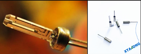
Soldering precautions of Tuning fork Crystal /Cylinder Crystal
Tuning fork Crystal (Cylinder Crystal ) User Manual and Soldering Precautions
Tuning fork Crystal , also known as a cylinder crystal , refers to a quartz crystal with a quartz chip that resembles a tuning fork in shape.
It is a crucial frequency electronic component in most electronic products involved in data processing, as it provides clock frequency.
Here is a summary of the instructions and soldering precautions for using a tuning fork/cylinder crystal :

Ultrasonic soldering:
Due to the internal quartz chip resonance, there is a risk of quartz chip damage when using ultrasonic soldering.
Therefore, it cannot be guaranteed whether ultrasonic soldering can be performed.
Oscillation criteria and conditions:
Excessive excitation power applied to the quartz chip can deteriorate its characteristics or cause non-oscillation. For this type of crystal oscillator, it is recommended to use it with a power below 1.0μW, with a maximum excitation power of 1μW (Maximum). It is not yet guaranteed for use above 2.0μW.
Shock resistance:
Excessive impact applied to the crystal oscillator can lead to deterioration of its physical characteristics or non-oscillation. Avoid dropping it and use it under conditions with minimal impact. When undergoing automatic soldering or changes in conditions, it is necessary to confirm thoroughly before use.
Heat resistance and moisture resistance:
Prolonged use and storage under high temperature, low temperature, or high humidity conditions can deteriorate the physical characteristics of the crystal oscillator. It is recommended to use and store it under normal temperature and humidity conditions as much as possible.
Solder heat resistance:
Standard crystal oscillators use solder with a melting point of 178℃. If the internal temperature of the crystal oscillator exceeds 150℃, it can deteriorate its characteristics or cause non-oscillation. When assembling under temperatures exceeding the mentioned temperature, consider using heat-resistant crystal oscillators or SMD crystal oscillators . When using flow soldering, please engineer confirm or contact the sales engineer at XTALONG ELECTRONICS for confirmation.Soldering conditions are as follows:
Lead section: Below 280℃ for 5 seconds or below 260℃ for 10 seconds.
Avoid directly soldering at the root of the lead, as it is a common cause of deterioration in crystal oscillator characteristics.Assembly method on PCB:
When the tuning fork crystal oscillator is placed horizontally, securely fasten it to the circuit board. Especially for vibrating parts, insert a cushioning material between the circuit board and the crystal oscillator or use adhesive with good elasticity (such as silicone) for fixation. Also, avoid applying adhesive to the base glass area.When using the crystal oscillator in an upright position, maintain a gap between the crystal oscillator and the circuit board:
Type 3*8: Above 3mm 3*8mm tuning fork crystal datasheet
Type 2*6: Above 2mm 2*6mm tuning fork crystal datasheet
Lead processing:
When cutting the leads, ensure that the cutting tool is adequately prepared.When processing the leads or bending them for adjustment, applying excessive force to the root of the leads can cause cracks in the base glass or inadequate sealing when applying excessive force to the insertion part. Additionally, leave a straight lead section of at least 0.5mm at the root of the leads.
