The Important Role of The Two External Capacitors of The RTC 32.768 khz crystal
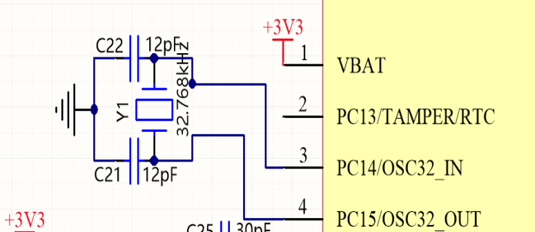
In general, the RTC 32.768 khz crystals (CL=12.5PF) pins are each connected to a capacitor of 18-22pF.
The full name of this type of MCU oscillation circuit is "three-point capacitor oscillation circuit".
The purpose of the two external capacitors is to fine-tune the frequency and to make the frequency more stable.
In terms of frequency trimming, the relationship between the external capacitor and the output frequency of
the passive crystal is inversely proportional. For details, please refer to the relevant articles on this website, so I will not repeat them here.
The role of external capacitors in stabilising the output frequency of passive crystals is analysed as follows.

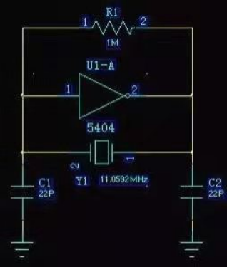
Passive crystal is equivalent to a three-point inside the inductor, C1 and C2 is the capacitor,
5404 non-gate and R1 for the realization of an NPN triode.
The 5404 necessarily requires a resistor, otherwise, it will be in the saturation cut-off zone, rather than the amplification zone.
r1 is equivalent to the biasing role of the triode so that the 5404 is in the amplification zone,
then the 5404 is an inverter, this realizes the role of the NPN triode. the NPN triode is also an inverter when the common emitter is connected.
Oscillation conditions for sinusoidal oscillation circuits:
The system amplification is greater than 1, i.e. the phase satisfies 360°. As the 5404 is an inverter, i
t can be phase shifted by 180°, so C1, C2 and Y1 are required to achieve a 180° phase shift.
When C1, C2, and Y1 form a resonance, they are able to achieve 180 phase shift. At resonance,
the currents passing through C1 and C2 are the same and the ground (GND) is between C1 and C2,
so the voltages are exactly opposite and the 180° phase shift is achieved. When C1 increases,
the amplitude of the C2 terminal increases, and when C2 decreases, the amplitude also increases.

Sometimes, C1 and C2 can be oscillated without soldering, not because there is no C1 and C2,
but because of the distributed capacitance of the chip pins.
There is another case where the chip is already internally configured with capacitors.
Because the 5404 voltage feedback is dependent on C2, assuming that C2 is too large,
the feedback voltage is too low, this is also unstable; assuming that C2 is too small, t
he feedback voltage is too high, the stored energy is too little, it is susceptible to external interference,
but also radiation will affect the outside world. The role of C1 on C2 is exactly the opposite.
Because in our wiring, assuming a relatively thick double-sided board,
the effect of the distributed stray capacitance will not be great.
But assuming a high-density multilayer board,
the distributed stray capacitance needs to be taken into account.
Suggestions
For some industrial control projects, it is recommended not to use the RTC 32.768 khz crystal ( passive crystal )solution,
also mainly due to the passive crystal needs to start the reason, and industrial control projects require stability to be good,
so will be through the direct choice of RTC 32.768 khz crystal oscillator (active crystal)
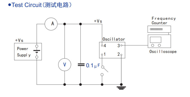
to obtain a more stable clock signal source. With RTC 32.768 khz crystal oscillator ( active crystal ) test circuit diagram as follows.

Click the below link to choose tuning fork crystal oscillator
http://www.xtalong.com/channel-74.html
